3.8 Flexible Liners
Flexible liners deployed in boreholes allow measurements of hydraulic conductivity, groundwater pressures, water quality, and NAPL distribution within a borehole and may also be used to conduct tracer tests and seal boreholes. Flexible liners have been developed to monitor landfills, augment horizontal drilling, provide groundwater pressure histories, and reline pipes and pull logging tools. Flexible liners are commercially available from Flexible Liner Underground Technologies, LLC (FLUTeTM). A depiction of a flexible liner and its insertion into a borehole are shown on Figure 3‑36.
Flexible liner measurement methods are simple and have been aided by the development of strong impermeable fabrics and the availability of data-recording pressure transducers. Because liners are deployed in open boreholes, they are typically used in bedrock.
Flexible liners can have multiple applications depending on the data needs of the investigation. When liners are used for multiple applications, a high-resolution dataset is generated at a borehole spatial resolution of several inches to several ft. Some applications can be performed with minimal training; others require trained FLUTeTM personnel to perform the installations and data reduction. The following applications of flexible liners are described in more detail in this section:
- sealing boreholes with liners
- mapping transmissivity profiles (FLUTeTM T Profiler)
- mapping NAPL distribution (NAPL FLUTeTM)
- mapping dissolved-phase contaminants [FLUTeTM Activated Carbon Technique (FACT)]
These applications often follow the numbered sequence above because they reuse the same flexible liner. The cost advantage of using FLUTeTM versus individual tools to achieve the same results is the multiple data streams that are derived from a single borehole and liner. In addition, FLUTeTM liners are readily removed unlike permanent subsurface installations.
3.8.1 Sealing Boreholes with Liners (FLUTeTM)
FLUTeTM liners are used to seal a borehole. The advantages of this method are:
- ease of installation and removal
- continuous seal quality
- support from the liner to protect the borehole wall against slough
- tracer arrival detection because of transparent liner
- geophysics logs can “see” through the liner from the protected interior;
- installation of liner without heavy equipment
- same liner can be used for multiple methods (NAPL FLUTeTM, FACT, FLUTeTM T profile, and the reverse-head profile).
Liners can be removed for repair or replacement if needed. Videos are available online from FLUTeTM to illustrate how to deploy liners, or a trained technician can be provided by FLUTeTM.
The liner is used to seal the borehole to prevent cross connection between zones of different hydraulic head. The basic blank liner is installed using eversion, which advances a liner downhole by turning it right side-out. To facilitate the process, the liner is shipped inside out to the site on a reel. The installation/removal process is as follows:
- Liner is pulled from the reel and secured to the borehole casing with a clamp.
- Liner is pushed down inside the casing, forming an annular pocket in the liner.
- Water is poured into the annular pocket; the weight of water in the liner causes the liner to evert down into the borehole, pulling the liner from the reel (see Figure 3‑36). A minimum height of water is needed to drive the everting liner to the water table. Water may be pumped from the borehole using a pump below the liner.
- Liner eversion stops at the water table, and more water is required to restore an excess head in the liner to continue eversion.
- Liner eversion below the water table displaces water into the formation.
- Liner descent by eversion continues until there is insufficient formation transmissivity beneath the everting liner to permit its further descent; at that time, the borehole is effectively sealed by the pressurized liner.
- To invert (remove) the liner, the operator pulls upward on the tether and water is drawn into the borehole until the liner is fully removed.
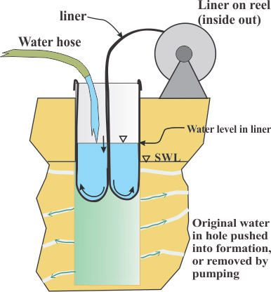
Figure 3‑36. Simple eversion of flexible liner.
Source: Flexible Liner Underground Technologies, Used with permission
Water-filled liners effectively seal boreholes by tightly conforming to the borehole wall and sealing around cavities and fractures in the formation. The seal of the liner with its conforming capability is better than that of most inflatable well packers which are made from stiffer materials.
The excess water head against the everting end of the liner causes tension to develop on the liner and the tether attached to the inside end of the liner. This tension is used for various applications such as towing logging tools into angled and horizontal boreholes or carrying tubing and other devices into the borehole. Water is the common driving fluid for liner eversion, but other fluids (such as heavy mud or air) may be used. Liners have been everted through crooked pipes and upward in boreholes from inside mine tunnels. Gamma, neutrons, and sonic and electrical signals may be measured through everting liners, allowing geophysicaltools to be deployed in the protective interior of the liner, which prevents borehole collapse and contamination of the tools.
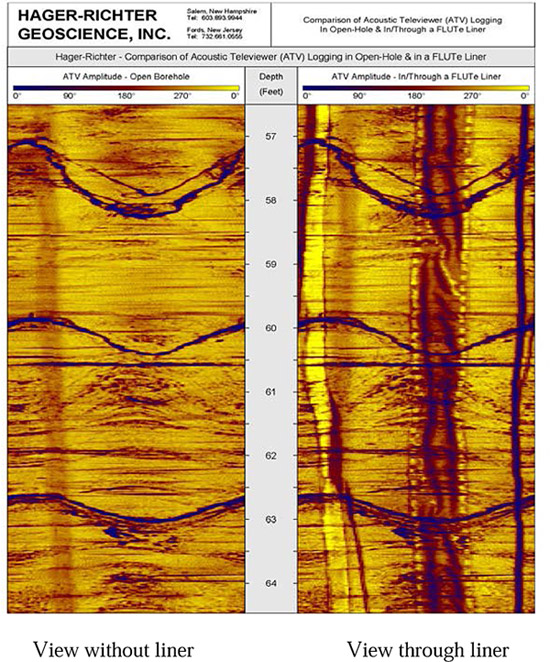
Figure 3‑37. Acoustic televiewer logs recorded with and without a liner in the same borehole.
Source: Flexible Liner Underground Technologies, Used with permission
An image of a borehole can also be obtained through both opaque and clear liners. In the case of opaque liners, an acoustic televiewer can be used to obtain the image. Figure 3‑37 shows views of an acoustic televiewer log (see Section 4.6) with (left) and without a liner (right). An interior sleeve (dark strip) and tether (right-most shadow) are visible in the view through the liner at right, but obscuration of the borehole wall by the liner is minimal; fracture locations are equally clear in both views. Transparent liners are also available, which may be useful to visually monitor the arrival of injected potassium permanganate within a borehole with a downhole camera.
3.8.2 Technical Limitations
Limitations when sealing boreholes with liners are as follows (for most sealing FLUTeTM and theFLUTeTM transmissivity profiler see Section 3.8):
- If the liner is exposed to extremely high concentrations of VOCs (NAPL), the VOCs diffuse into the liner interior water. Upon removal, the water must be treated as contaminated.
- Some compounds such as potassium permanganate degrade nylon liners; polyester liners are available for sites with potassium permanganate in groundwater.
- The water level in the liner must be maintained to preserve the seal of the liner.
- For extreme downward gradients (>50 ft over the borehole depth), a stronger liner is required to prevent the liner from bursting.
- Although liners can be punctured by sharp rocks in the borehole wall, puncturing has only occurred in fewer than 1% of liner installations.
The limitations of the NAPL FLUTeTM liner include the following:
- An open stable hole or installation through drill casing is required.
- The dissolved phase is not detectable, and the liner must contact NAPL for a stain to develop.
- Solvents migrate in the cover material and, therefore, the size of the stain is not indicative of NAPL thickness.
- The NAPL type cannot be identified by the stain.
- Stains represent current NAPL locations; NAPL may be redistributed by the drilling process, resulting in scattered staining. (Scattered small stains usually occur in boreholes with large stains from the source of the scattered NAPL).
3.8.3 FLUTeTM Transmissivity Profiler
The liner descent rate in a water-filled borehole can be used to map the location and flow rates of water in the fractures intersecting the borehole. However, the procedure requires that the excess head driving the liner and the tension on the liner be maintained relatively constant. Under these conditions, the liner suffers a drop in its descent velocity each time a flowing fracture is sealed by the descending liner. The velocity change multiplied by the cross-sectional area of the borehole is the flow rate of the water in the fracture before it was sealed.
The transmissivity of the interval traversed by the liner in one recording time step is calculated using the Thiem equation:
ΔT = ΔQ/ΔHh ln(ra/rh)/2π = (vi-vi+1) A ln(ra/rh)/(2π(Hh-Ha))
where ΔQ is the change in velocity (vi) multiplied by the borehole cross section (A), ΔHh is the difference between the borehole pressure (Hh) and the ambient pressure (Ha) in the formation at a distance (ra) from the borehole center, and rh is the borehole radius. Since ra is often not well known, it is estimated.
Because it occurs in the long term, an error in the ratio is not a major error in the calculation. The spatial interval is dependent upon the recording time step (typically 0.5 sec) and the velocity of the liner. In other words, the faster the liner descents, the longer the interval traversed in one-time step. For example, when integrated over 1-ft intervals, the result is similar to that obtained from a series of 1-ft-long straddle packer tests.
3.8.4 The NAPL FLUTeTM Liner
The NAPL FLUTeTM liner maps the distribution of NAPL present at the borehole wall against the hydrophobic liner cover. Upon contact with NAPLs, dye in the liner is dissolved, producing a dark stain on the inside white surface of the hydrophobic cover. Stain colors vary from purple (a mixture of the dyes used) to dark brown or nearly black if the NAPL is mixed with oily residue as a spent solvent. The hydrophobic cover reacts only with pure NAPL, not dissolved-phase contamination, creating a visual log of free-phase product within the borehole, if present.
Advantages of the NAPL FLUTeTM liner are as follows:
- Stains observed are a reliable indication of the presence of NAPL at any depth within the borehole.
- Stains indicate the presence of NAPL not apparent through visual observation of a rock core.
- Stains are easy to observe and photograph and require minimal interpretation.
- Spatial resolution of NAPL is approximately 1 inch to 2 inches and presents a full 2-D map of the presence of NAPL.
- The NAPL FLUTeTM liner is a relatively inexpensive addition to a sealing liner used to prevent cross connection.
Many compounds have been tested for reactivity with the NAPL FLUTeTM liner; a list is available online from FLUTeTM. To confirm reactivity, a confirmation staining test of the target NAPL with the FLUTeTM liner material should be conducted prior to employing a FLUTeTM liner investigation program.
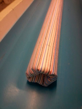
Figure 3‑38. Everted dye-striped NAPL FLUTeTM liner cover.
Source: Flexible Liner Underground Technologies, Used with permission
When everting the NAPL FLUTeTM liner into a borehole, one borehole volume of water is pumped from beneath the liner during installation to reduce the injection of water into the fractures (the injection effect may displace NAPL from the borehole vicinity). Pumping should not be excessive so that significant mobilization of NAPL is avoided. It is important to note that water displaced into fractures during the eversion is likely extracted from the same fractures during the inversion of the liner from the borehole.
After a minimum of one hour, the liner is inverted from the borehole as shown on Figure 3‑38. The dye-stripe liner cover is now inside of the inside-out liner. The liner cover is held as the liner is slipped off the liner cover, exposing the normally white inside surface of the liner. Visible stains on the white surface of the line indicate where NAPL has contacted the liner cover. A tape measure is placed next to the cover, and the stains are photographed to record the depth in the hole where NAPL contacted the liner cover.
Because the liner and liner cover are inverted from the borehole, the liner cover does not contact any other portion of the borehole than where it was everted against the borehole wall. The NAPL FLUTeTM cover is often installed on the blank liner for the initial emplacement to seal the borehole. Upon removal of the NAPL FLUTeTM cover, the liner is replaced to seal the borehole or perform other measurements described below.
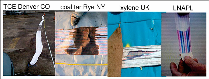
As an example, Figure 3‑39 shows stains from TCE, coal tar, xylene, and gasoline on the inside surface of a cover. The first three stains were obtained in open fractured rock boreholes, which are the conditions where this method is most commonly used. The LNAPL stain was the result of a thin gasoline film on water in a tube.
Figure 3‑39. Examples of NAPL stains on the inside surface of a cover.
Source: Flexible Liner Underground Technologies, Used with permission
Rather than being deployed downhole, the NAPL FLUTeTM cover material may also be used as a bag to detect NAPL in extruded core material that is placed inside the bag. This technique is used if the borehole is not expected to remain open when casing is removed or if only a small section of core is to be tested. Similar to the liner, contact of NAPL in the core with the dye on the inside surface of the bag will produce a visible stain on the outside of the bag.
3.8.5 FLUTeTM Activated Carbon Technique
The NAPL FLUTeTM liner, described above, detects only NAPL in contact with the cover, but the FACT can detect contaminants in the pore space and in fractures of the formation at the borehole wall. The NAPL FLUTeTM liner and FACT may be deployed together, generating two datasets from the same borehole.
In the FACT, an activated carbon felt strip is pressed against the borehole wall when the sealing liner is everted into the borehole. The FACT strip is left in the borehole for up to two weeks during which the carbon adsorbs the dissolved phase of the contaminants.
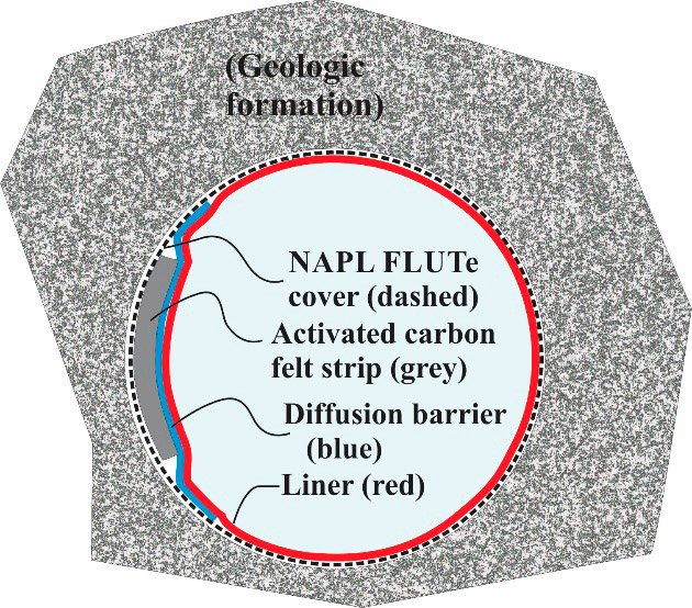
Figure 3‑40. FACT components.
Source: Flexible Liner Underground Technologies, Used with permission
The construction of the FACT is shown in Figure 3‑40. The FACT carbon strip (about 1.5-inches wide and 0.125-inches thick) is contained between the outer NAPL FLUTeTM cover material (dashed curve) and a diffusion barrier (blue) that is sewn into the inside surface of the thin (about 1 mil) cover material. The pressurized liner (red line) presses the diffusion barrier (blue line), the carbon felt (gray line), and the NAPL FLUTeTM cover (dashed line) against the borehole wall.
After two weeks in the borehole, the liner is inverted from the borehole with the NAPL FLUTeTM cover. As described in Section 3.8.4, the liner is slipped off the inverted cover, and NAPL stains, if present, are photographed. The diffusion barrier, which is now on the outside of the inverted cover, is slit and the carbon felt strip is removed, cut to desired lengths, and inserted into sample jars filled with deionized water. Carbon-felt samples are shipped to a laboratory for analysis according to USEPA Method 8265. Acceptable performance for the carbon-felt matrix should be demonstrated by matrix spikes or laboratory control samples with analytes spiked onto the carbon felt.
The spatial resolution of data is determined by the length of each carbon-felt strip, which is determined by the user. For a high-resolution dataset, the carbon strips may be cut into small (6 inch) pieces; for a lower resolution dataset, the carbon strips may be cut into larger (1 ft to 2 ft) pieces. Analyzing larger sections of FACT is less costly because fewer samples are generated, but a data set with lower resolution results. Regardless of sample length, the entire carbon strip must be analyzed because contaminants do not migrate in the carbon; failure to analyze the entire length of carbon can result an interval of elevated contamination being missed.
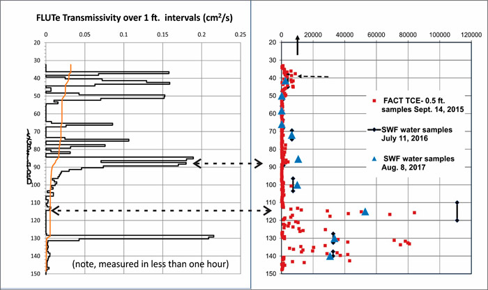
The right side of Figure 3‑41 shows measurements of TCE (in ppm of carbon) in 6-inch carbon-felt segments from a 150-foot borehole using the FACT. The graph also shows corresponding groundwater concentrations [in parts per billion (ppb)] obtained from 10 sample intervals 300 days (black bars in figure) and 700 days (blue triangles in figure) after the FACT carbon strip was removed. Water samples are plotted on the same scale regardless of unit, which shows the distribution similarity. The data comparison between the FACT and water sample results shows the accuracy of the measurements from the FACT and how the liner prevents borehole cross connections between different contaminated zones. The water samples are derived mainly from fracture flows, suggesting that the FACT is also sensitive to fracture flow concentrations. Because the FACT produces a diffusion-based measurement, contaminant concentration gradients are expected to be highest for water flowing past the FACT carbon strip as compared to water trapped in the pore space of the matrix. Thus, the mass of diffusion is directly dependent on the concentration gradient.
Measurements from the FACT generally agree with the contaminant concentration distribution in the core, but not necessarily with all locations in the borehole. The FACT draws from pore water and fracture water, whereas a core assessment measures the pore water of selected samples, not the entire core, or intervals of lost core. FLUTeTM is often a component of a DFN investigation (see Section 3.1.7.2), so a high-resolution comparison may be performed when both investigation methods are used.
Figure 3‑41. FACT results with transmissivity.
Source: Flexible Liner Underground Technologies, Used with permission
The left side of Figure 3‑40 shows transmissivity over the intervals, providing a side-by-side comparison of the FACT results and the transmissive intervals measured. The arrows correlate two example high concentration intervals to corresponding transmissivity intervals. The highest concentrations are not always in the high flow zones. The highest concentration at 115 ft occurs within a low-transmissivity interval, and the relatively low concentration at 87 ft occurs within a high-transmissivity interval.
The FACT uses carbon-felt strips, which contain toluene that is known to be leached from the urethane-coated liner fabric. Leaching is unlikely to impact future water samples because the toluene dissipates relatively quickly from the liner, but not in the time frame of the FACT installation, and therefore will be seen in the analysis of the carbon strip.
Advantages of the FACT:
- Provides a continuous vertical map of the dissolved-phase contaminants (the entire length of the borehole is evaluated so no intervals are missed).
- Not dependent on prior judgement of where contaminants are residing.
- Results correlate to groundwater samples.
- Sensitive to both pore-space and fracture contamination.
- Can be added to the NAPL FLUTeTM cover at relatively small additional cost.
- Carrier liner can be reused to seal the borehole or to perform other high-resolution measurements.
Click here to download the entire document.

