• Skip to main content
itrc_logo

Implementing Advanced Site Characterization Tools

Navigating this Website
1 Introduction
1 Introduction Overview
1.1 Purpose and Scope
1.2 Technologies
1.3 How to Use this Document
2 ASCT Implementation
2 ASCT Implementation Overview
2.1 Tool Selection
2.2 Tool Application
3 Direct Sensing
3 Direct Sensing Overview
3.1 How to Select and Apply Direct Sensing Tools Using this Document
3.2 Membrane Interface Probe
3.3 Optical Image Profiler
3.4 Laser-Induced Fluorescence
3.5 Cone Penetrometer Testing
3.6 Hydraulic and Groundwater Profiling Tools
3.7 Electrical Conductivity (EC) Probe
3.8 Flexible Liners
4 Borehole Geophysics
4 Borehole Geophysics Overview
4.1 How to Select and Apply Borehole Geophysical Tools Using this Document
4.2 Fluid Temperature
4.3 Fluid Resistivity
4.4 Mechanical Caliper
4.5 Optical Televiewer
4.6 Acoustic Televiewer
4.7 Natural Gamma Logging
4.8 Borehole Flow Meters
4.9 Advanced Borehole Logging Tools
5 Surface Geophysics
5 Surface Geophysics Overview
5.1 How to Select and Apply Surface Geophysical Tools Using this Document
5.2 Electrical Resistivity Imaging
5.3 Ground Penetrating Radar
5.4 Seismic Methods
5.5 Electromagnetic Surveys
6 Remote Sensing
6 Remote Sensing Overview
6.1 How to Select and Apply Remote Sensing Tools Using this Document
6.2 Drones
6.3 Visible Spectrum Camera
6.4 Camera Features
6.5 Photogrammetry
6.6 Sample Collection and Monitoring using Drones
6.7 Cost Considerations
6.8 Case Studies
7 Stakeholder and Tribal Perspectives
8 Regulatory Perspective
8 Regulatory Perspective Overview
8.1 Challenges and Solutions
9 Case Studies
9 Case Studies Overview
9.1 MIP Boring Data Allow On-Site Decisions to Fill Data Gaps and Reduce Uncertainty during Triad Approach Evaluation at Five South Dakota Sites
9.2 MIP Allows Real-Time Identification and Delineation of DNAPL Plume at a Former Naval Air Station in California
9.3 OIP-Green Probe Delineates Extent of Coal Tar NAPL at a Former Gas Manufacturing Plant in Kansas
9.4 LIF Survey with UOVOST® Provides More Accurate Representation of LNAPL Plume at a Former Bulk Petroleum Storage Facility in New Hampshire
9.5 UVOST Differentiates LNAPL Types to Allocate Financial Liabilities at a Retail Petroleum Facility in Tennessee
9.6 TarGOST Determines DNAPL Extent and HPT Confirms Site Lithology at a Former Creosote Facility in Louisiana
9.7 CPT Borings and Hydropunch Sampler Optimize Site Characterization at an Aviation Industrial Complex in California
9.8 Waterloo APS, CPT, and LIF Data Update CSM and Help Optimize Selected Remedy at a Former Refinery in Oklahoma
9.9 Conceptual Site Model Development Using Borehole Geophysics at the Savage Municipal Water Supply Superfund Site in New Hampshire
9.10 ERI Provides Data to Improve Groundwater Flow and Contaminant Transport Models at Hanford 300 Facility in Washington
9.11 Surface and Borehole Geophysical Technologies Provide Data to Pinpoint and Characterize Karst Features at a Former Retail Petroleum Facility in Kentucky
9.12 GPR Data Show Location of Buried Debris and Piping Associated with a Former Gas Holder in Minnesota
9.13 Resistivity, Seismic Exploration, and GPR Provide Data to Evaluate Clay Reserves at a Commercially Mined Pit
9.14 Seismic Refraction, Electric Resistivity, and Multichannel Analysis of Seismic Waves Provide Data to Locate Monitoring Well Locations in a Mixed-Use Area in Northern Virginia
9.15 Surface Geophysical Methods Provide Data to Identify Prospective Utility Waste Landfill Sites in Karst Terrain in Missouri
9.16 Airborne Time-Domain Electromagnetic Method Maps Sand Distribution along the Illinois Lake Michigan Shore
9.17 Drone Technology Expedites and Streamlines Site Characterization at a Former Golf Course in Missouri
9.18 High-Resolution and Thermal Aerial Images Identify Mine Openings at an Abandoned Colorado Mine
9.19 RPAS Collects Water Samples to Avoid Safety Concerns at Montana Tunnels Mine
Additional Information
Appendix A. Tool Tables and Checklists
Glossary
References
Acronyms
Acknowledgments
Team Contacts
Document Feedback


Click for Selection Tool Click for Summary Tables Click for Tool Descriptions Click for Case Studies Click for Checklists Click for Training Videos Click for Home

9.19 RPAS Collects Water Samples to Avoid Safety Concerns at Montana Tunnels Mine

Devin Castendyk, PhD, MSc
Senior Geochemist
Golder Associates Inc.
Denver, Colorado
[email protected]

On October 23, 2018, a three-person team from Golder Associates Inc. (Golder) in Denver, Colorado, collected three water samples in the Montana Tunnels Pit Lake near Jefferson City, Montana. Water quality monitoring was conducted for the first time at a flooded former open pit gold mine (now known as the Montana Tunnels Pit Lake) near Jefferson City, Montana. The use of a remotely piloted aircraft system (RPAS) avoided the significant safety risk of posed by unstable pit walls. Three water samples were collected from 0- , 92-, and 184-ft deep.

The work was contracted by the MDEQ and observed by representatives from the MDEQ, U.S. Bureau of Land Management (BLM), and Montana Tunnels Mining Company. (Williams et al. 2018) described this sampling event in an inspection report, copies of which can be requested from the Butte, Montana office of the BLM.

The RPAS was flown above a point on the water surface that was believed to overlie the deepest location within the pit lake. Flight 1 lowered a CastAway CTD through the water column that recorded the maximum depth (230 ft) and measured in situ profiles of temperature and electrical conductivity. Temperature and electrical conductivity were uniform throughout the water column, indicating that the lake had recently undergone complete mixing through a process known as fall turnover (see Figure 9‑69).

Based on evidence of homogeneous conditions in the water column, three water samples were collected with uniform sample spacing across the water column. After discussions with MDEQ, sample depths of 0 ft, 98 ft, and 197 ft were targeted for sampling. Flight 2 collected a two litre (2L) water sample from the deepest depth. Flight 3 attempted to collect a sample from the immediate surface of the water, but upon return, the sample chamber contained only 0.6 L. Flight 4 lowered the sampling device a few feet deeper and returned with a 2L sample. Flight 5 collected a 2L sample from the mid-depth of the lake. Postprocessing of pressure transducer data showed the actual sample depths to be 0-, 92-, and 184-ft deep.

The sampling event provided data to meet MDEQ requirements and demonstrated the ability of aerial drones to perform water sampling. Given that the original request for proposals required only two water samples from 10- and 50-ft deep, the sampling team was able to provide an additional sample and significantly greater vertical distribution than requested at no additional charge. Most importantly, use of RPAS water sampling equipment significantly improved safety compared to boat-based methods. The MDEQ accepted the samples for routine monitoring purposes.

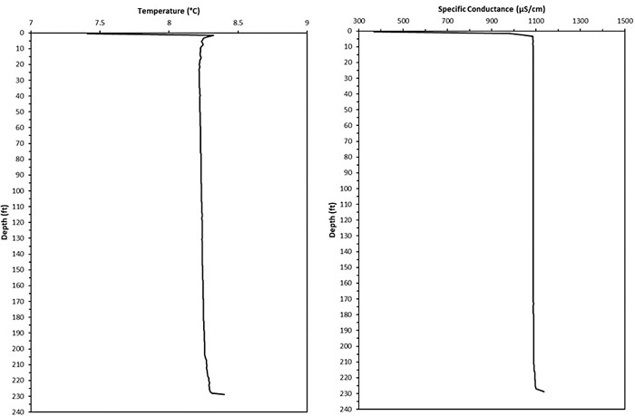
Figure 9‑69. In situ temperature (left) and specific conductivity (right) measured in the Montana Tunnels pit lake on October 23, 2018.

image_pdfPrint this page/section
Click here to download the entire document.


ASCT-1

web document
glossaryASCT-1
Glossary
referencesASCT-1
References
acronymsASCT-1
Acronyms

ITRC
Contact Us
About ITRC
Visit ITRC
social media iconsClick here to visit ITRC on FacebookClick here to visit ITRC on TwitterClick here to visit ITRC on LinkedInITRC on Social Media
Permission is granted to refer to or quote from this publication with the customary acknowledgment of the source (see suggested citation and disclaimer). This web site is owned by ITRC • 1250 H Street, NW • Suite 850 • Washington, DC 20005 • (202) 266-4933 • Email: [email protected] • Terms of Service, Privacy Policy, and Usage Policy ITRC is sponsored by the Environmental Council of the States.