
9.11 Surface and Borehole Geophysical Technologies Provide Data to Pinpoint and Characterize Karst Features at a Former Retail Petroleum Facility in Kentucky
| Michael Albright KY Underground Storage Tank Branch Frankfort, KY [email protected] |
Brad Highley KY Underground Storage Tank Branch Frankfort, KY [email protected] |
| Information presented in this case study is based on investigations conducted by Mundell and Associates, Hinkle Meyer Environmental Services, and Shield Environmental Associates – See source information below. | |
Many UST sites in Kentucky are located within the four distinct karst areas underlying the Commonwealth. Karst geomorphology and hydrogeology create unique challenges to effectively characterizing contaminant location and extent as well as characterizing flow dynamics at these sites. Traditional characterization of UST releases in karst terrain involves the initial collection of soil samples (saturated and unsaturated) and groundwater samples from the water table aquifer. Monitoring wells are often installed in rock without adequate knowledge of the karst geomorphology and hydrogeology specific to the point of installation. Monitoring wells thus installed typically provide insufficient information regarding contaminant mass in the epikarst, in solution-enhanced fractures, and in well-developed karst conduits. To address this insufficiency, surface geophysical methods such as two-dimensional ERI, refraction micro tremor, frequency domain electromagnetic conductivity, and low-frequency electromagnetics were used to identify potential bedrock monitoring well locations. Once the borehole was established, geophysical methods, including caliper, gamma log, borehole resistivity, optical televiewer, acoustic televiewer, and heat-pulse flowmeter are employed. Combining these methods increases well-placement efficiency, which supports effective site characterization.
A recent investigation conducted at a former retail petroleum facility in the Eastern Pennyroyal Karst Area near Mt. Vernon, Kentucky demonstrates the critical importance of implementing borehole geophysical technologies to characterize contaminant mass storage and transport in karst terrain. The B&F Gulf Service Station has an extensive history of environmental and public health issues such as vapor in adjacent off-site structures, LNAPL in public utility lines, and LNAPL in off-site monitoring wells. While site investigations spanning the last 20 years had determined that minor amounts of LNAPL and gasoline contaminants are present in overburden soil, shallow epikarst features, and deeper karst features, traditional investigation methods failed to produce sufficient data for construction of a comprehensive conceptual site model. Surface geophysical investigations were performed to identify additional monitoring well locations. Once the new boreholes were established, borehole geophysical logging was performed to 1) locate, differentiate, and map the differing lithologic units underlying the sites; 2) locate and identify karst features, fractures, and bedding planes that may be acting as pathways for the transport and distribution of contaminants; 3) determine the construction of monitoring wells; and 4) refine the CSM.
To characterize the perceived karst terrain underlying the site, a surface geophysical survey was performed in August 2015. Given the required imaging depth of 20 ft to 50 ft below ground surface and the desire to image the vertical and horizontal extent of subsurface features, the survey included seven ER profiles along with FDEM and GPR (see Figure 9‑40). This approach was selected because unfractured carbonate rocks in karst terrains are highly resistive and fractured and solution-enhanced rocks have lower resistivity values. When combined with known lithological and structural information, these anomalies can help identify and characterize karst features often at great depths. ER data was collected using an Advanced Geosciences SuperSting™ R8 earth-resistivity meter; FDEM data was collected using a GEM-2 broadband electromagnetic sensor manufactured by Geophex LTD. The surface geophysical survey identified:
- Numerous karst features (sinkholes, springs) during field reconnaissance.
- Several clay and residuum-filled sinkholes
- Several local vertically-aligned low-resistivity zones within the limestone bedrock possibly acting as preferential flow paths, both vertically and horizontally.
- Solution- enhanced fractures and bedding planes are possibly acting as reservoirs and conduits for contaminant transport.
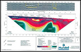
Figure 9‑40. Electrical Resistivity and GPR Profile Line 3
To verify these findings, five boreholes were advanced and logged near the B&F Gulf site in October 2016. In May 2018, two additional boreholes were advanced and logged geophysically. Drilling locations were determined using prior surface geophysical survey data. Borehole logging was performed using an optical televiewer probe, acoustic televiewer probe, natural gamma probe, three-arm caliper probe, and EM resistivity probe. The selected tools will allow for well installation in relation to karst features which may be acting as reservoirs and conduits for LNAPL and dissolved phase petroleum hydrocarbons.
Borehole geophysical logging results indicated the following:
- Solution-enhanced fractures and bedding planes are acting as reservoirs and conduits for contaminant transport.
- Borehole logging with the optical televiewer tool identified the presence of LNAPL at the soil\bedrock interface and in the epikarst. The LNAPL is most likely the source of vapor intrusion (see Figure 9‑41). Historical vapor intrusion investigations failed to identify the source of petroleum vapor intrusion in adjacent structures.
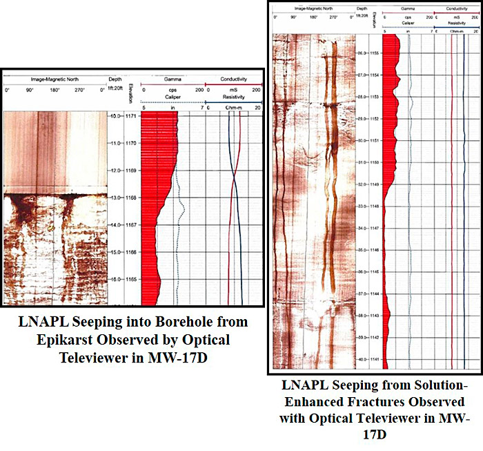
Figure 9‑41. LNAPL observed by optical televiewer
The total cost for the surface and borehole geophysical investigations at the site was approximately $83,600. Specifically, the cost of the surface geophysical field investigation and analysis was $16, 800 with an additional $7,000 for project management. The cost of the borehole geophysical investigations was approximately $59,800, which included $37,700 for borehole geophysical logging and $22,100 for borehole advancement and monitoring well installation.
While these costs, and the cost of geophysical investigations in general are significant, the resulting high-resolution datasets allowed the appropriate placement of horizontal and vertical monitoring wells as well as the determination of the appropriate screened interval. This reduced the overall cost and duration of the site characterization and facilitated CSM refinement, which ultimately will lead to timely and cost-effective site remediation.
9.11.1 Source Information
Report of Geophysical Survey: Subsurface and Bedrock Mapping, Former B&F Gulf Service Station, Mt. Vernon, KY, Mundell and Associates, Former B&F Gulf Service Station, Mt. Vernon, KY, Shield Environmental Associates, Hinkle Meyer Environmental Services, November 4, 2015
Intermediate Site Investigation Report, Former B&F Gulf Service Station, Mt. Vernon, KY, Shield Environmental Associates, Hinkle Meyer Environmental Services, January 25, 2017
Report of Geophysical Survey: Geophysical Borehole Logging, Former B&F Gulf Service Station, Mt. Vernon, KY, Mundell and Associates, Shield Environmental Associates, Hinkle Meyer Environmental Services, January 24, 2017
Preliminary Report of Geophysical Survey: Geophysical Borehole Logging, Former B&F Gulf Service Station, Mt. Vernon, KY, Mundell and Associates, Shield Environmental Associates, Hinkle Meyer Environmental Services, May 2018
Click here to download the entire document.

